


Standardized Metal Microstructure Inspection: A Practical ASTM & ISO Workflow for Export-Grade Consistency
In global B2B manufacturing, microstructure verification is no longer “lab-only”—it is a passport for export compliance, stable heat treatment, and reliable supplier qualification. This guide explains a standardized, repeatable metallography workflow aligned with commonly used ASTM and ISO practices, from sample preparation to microscope settings, image traceability, and quality control.
Why Standardization Matters in Microstructure Testing (and Why Buyers Care)
For export-oriented metal products—gears, fasteners, forged parts, castings, bearings, tool steels—microstructure is a direct indicator of whether heat treatment and processing are under control. Many overseas customers audit suppliers based on “evidence quality”: reproducible test methods, traceable images, and comparable results across labs. A standardized microstructure inspection process reduces disputes such as “same part, different conclusion,” especially when multiple parties are involved (supplier lab, third-party inspection, and customer lab).
In practice, inconsistency most often comes from small variables: sectioning direction, grinding sequence, polishing cloth choice, etchant concentration, microscope illumination, or mismatched magnification. A controlled workflow can typically improve inter-operator repeatability by 20–40% in common rating tasks (e.g., inclusion rating or grain size) and cut rework loops from days to hours when documentation is complete.
Commonly referenced standards in daily metallography: ASTM E3 (specimen preparation), ASTM E407 (etching), ASTM E112 (grain size), ASTM E45 (inclusions), ISO 643 (steel grain size), ISO 4967 (non-metallic inclusions), ISO 17639 (weld macro/micro examination).
A Standardized End-to-End Workflow (ASTM/ISO-Aligned)
1) Sampling Plan and Section Orientation: start with what you want to prove
A microstructure result is only meaningful when the sampling position and cutting direction match the functional risk. For forged and rolled products, the L/T/S direction (longitudinal/transverse/short transverse) affects banding, elongation of inclusions, and anisotropy. For heat-treated components, select sections that capture the most critical thermal gradient areas (surface vs. core), especially in larger cross-sections.
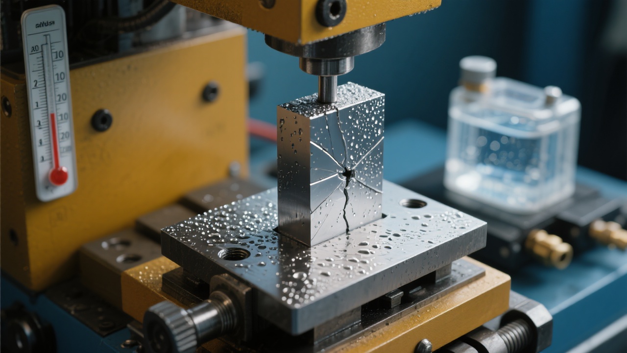
As a practical baseline, many labs control sectioning geometry using: 90° cross-sections for general structure comparison, 0°/parallel sections to reveal flow lines, and 45° sections to highlight certain crack paths. Where relevant, record the orientation with a simple sketch in the test report to prevent interpretation drift between parties.
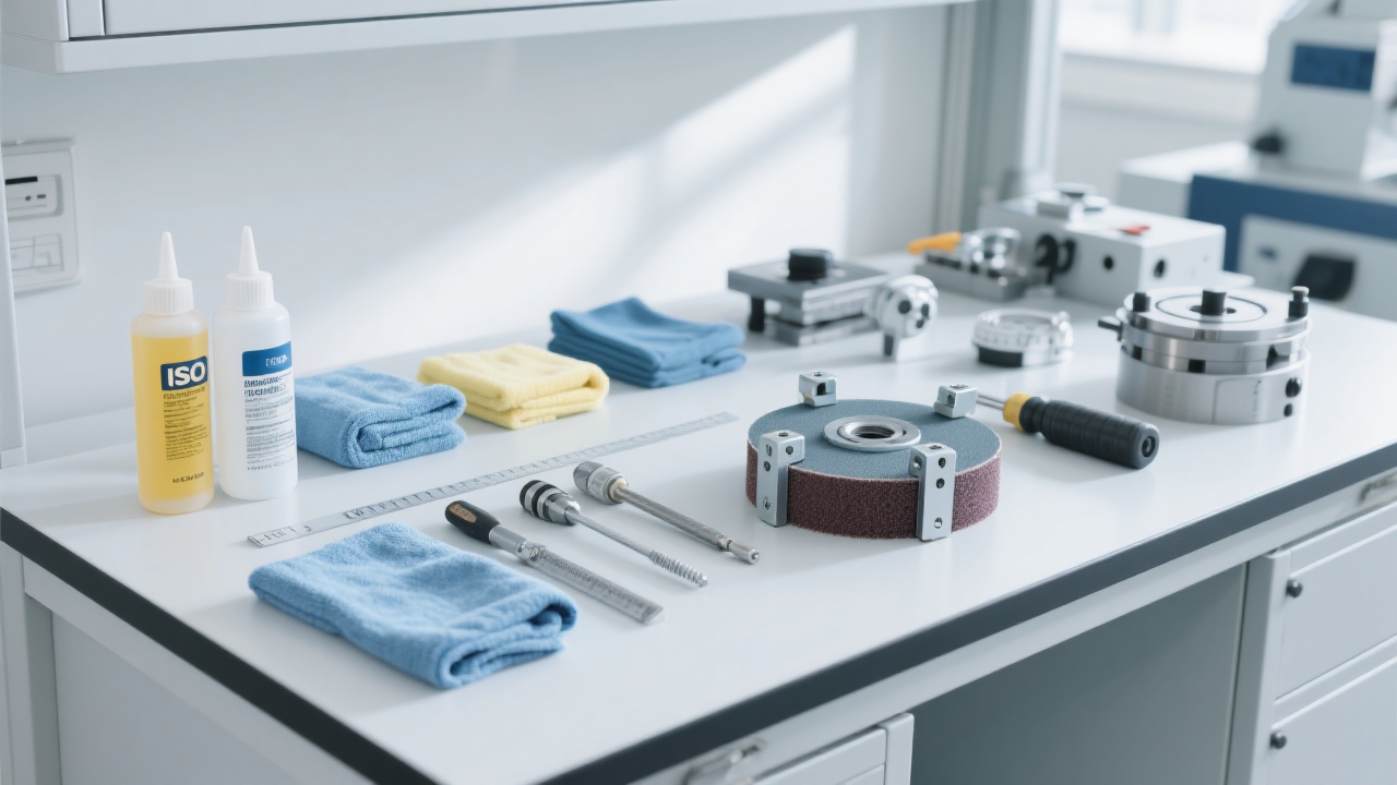
2) Mounting, Grinding, and Polishing: repeatability is built here
ASTM E3-style preparation emphasizes controlling deformation and avoiding artifacts. For routine steel microstructures, a common, repeatable sequence is: P240 → P400 → P800 → P1200 grinding, followed by polishing with 6 μm → 3 μm → 1 μm diamond suspension, then a final finish if needed (e.g., 0.05 μm colloidal silica for challenging alloys).
Two export-grade habits matter more than “perfect shine”: (a) keep grinding direction changes consistent and long enough to remove the previous scratches; (b) control pressure and time so the microstructure is not plastically smeared. For inclusion rating or grain size, preparation artifacts can shift a borderline decision and trigger customer claims.
3) Etching Selection (ASTM E407 logic): choose chemistry to reveal the right contrast
Etching is not a ritual—it is a contrast tool. For steels, 2–4% Nital is widely used for ferrite/pearlite and tempered martensite contrast. For stainless steels, reagents like glyceregia or electrolytic methods may be preferred depending on alloy class and targeted features. For aluminum alloys, Keller’s reagent is common when grain boundaries and second phases must be visible.
To improve inter-lab comparability, many quality teams record etch parameters as “recipe + time + temperature + agitation,” for example: 3% Nital, 8–12 s, 22–25°C, gentle swab. This small discipline often prevents “over-etch vs under-etch” arguments during customer audits.
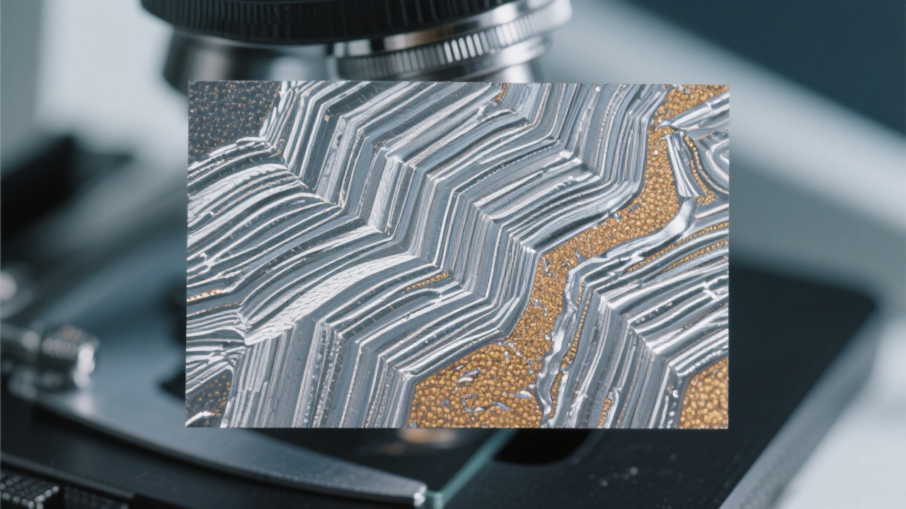
4) Microscope Settings: magnification alone does not standardize results
Microstructure inspection requires consistent optics and imaging behavior. A robust standard operating practice typically defines: illumination mode (brightfield by default), white balance/color calibration, aperture/contrast, objective plan grade, and image resolution. Without color/brightness control, operators may “dial in” contrast differently and unintentionally bias inclusion or carbide visibility.
As a workable magnification map: 50×–100× for general structure and banding screening, 200×–500× for inclusion assessment and carbides, and 500×–1000× for fine features (with caution: higher magnification increases sensitivity to polishing artifacts). When standards specify evaluation magnifications (e.g., inclusion rating), always follow the standard first, then add “engineering images” as supplementary evidence.
5) Image Capture and Traceability: make every micrograph audit-ready
Buyers rarely dispute a clean, traceable image set. A practical documentation template includes: part ID/heat number, sampling location and orientation, preparation route, etchant and time, microscope model/objective, magnification, scale bar, date/time, operator, and acceptance criteria reference (ASTM/ISO clause or internal spec). In many factories, adopting this template reduces “re-test requests” by 15–25% because evidence is complete the first time.
For data integrity, store original images (lossless or high-quality format), keep an unedited version, and log any post-processing (cropping, annotation). If a customer asks for raw files during an audit, the lab can respond in minutes rather than days.
Quality Control Essentials: Turning Micrographs into Decisions
Heat Treatment Conformance: what microstructure should “look like”
Microstructure is one of the fastest ways to verify whether heat treatment is fundamentally correct. For many steels, laboratories look for expected phase balance and morphology: ferrite/pearlite ratio in normalized conditions, martensite formation after quenching, carbide distribution after tempering, and evidence of overheating (coarsened grains) or underheating (incomplete transformation).
A disciplined approach is to define “acceptance microstructures” with reference images (internal library) tied to process windows and hardness ranges. For example, a stable quench-and-temper line often correlates to a hardness window that stays within ±2 HRC lot-to-lot, while the microstructure confirms whether that hardness comes from the right transformation rather than an accidental surface effect.
Defect Identification: inclusions, cracks, and what they imply
Standardized microstructure testing helps separate true defects from preparation artifacts. Non-metallic inclusions are often rated against reference methods (commonly aligned with ASTM E45 or ISO 4967) to support supplier qualification and clean steel requirements. Cracks, laps, decarburization, and abnormal banding can be traced back to forging, machining, surface treatment, or heat treatment stages.
A useful practice in export QC is “defect-to-process mapping”: once the lab classifies defect type and location, the report links it to the likely upstream cause and the corrective action owner. This closes the loop and prevents repeated claims from the same root cause.
Inter-Laboratory Comparison and Data Governance: how to keep results authoritative
When exporters work with third-party inspectors or overseas customer labs, round-robin comparisons are the fastest way to build trust. A typical method is to share the same specimen set and compare: preparation route adherence, magnification compliance, and ratings (grain size, inclusion class, defect calls). If the deviation exceeds a pre-agreed limit (for example, grain size rating difference greater than 0.5 in ASTM E112 reporting), the team investigates preparation and imaging variables first.
On the data side, a simple “three-layer” governance model is practical: raw images (immutable archive), annotated reporting images (with scale bar and labels), and structured results (ratings, decisions, clauses) stored in a searchable database. This supports fast customer response, trend analysis, and continuous improvement.
Quick Reference: A Practical Standardization Checklist
- Record sampling location + orientation sketch (L/T/S when relevant).
- Lock a preparation route (abrasives, grit sizes, polishing media, time/pressure).
- Standardize etch recipe and timing; log temperature and method.
- Fix microscope presets: illumination, white balance, magnification map, resolution.
- Export-ready traceability: scale bar, objective info, operator, date, acceptance clause.
- Quarterly inter-lab comparison or internal proficiency checks.
Where Equipment Choice Quietly Affects Standardization
Standardization is a method first—but the microscope is the tool that must reproduce that method day after day. In many real factories, the bottleneck is not knowledge; it is stability: illumination drift, inconsistent color rendering, limited documentation features, or difficult image capture workflows. When QC teams scale across shifts, these details become measurable risk.
In this context, metallurgical microscopes designed for routine inspection can make standardization easier to sustain. For example, the Laizhou Jincheng Industrial Equipment Co., Ltd. 4XC-W metallurgical microscope is often selected for metallography workflows where teams need clear imaging, repeatable operating presets, and efficient technical support for method setup and operator training—especially when building an export-facing inspection system that must stand up to audits and customer comparison tests.
Want a repeatable metallography workflow on your shop floor?
Get a practical microscope configuration checklist, recommended magnification map for your material, and guidance for aligning your lab reports with ASTM/ISO expectations.
Explore the 4XC-W Metallurgical Microscope & Technical SupportIdeal for QC labs, R&D centers, and university metallurgy teaching labs that need consistent microstructure imaging and traceable reporting.

Hardness-Tester7MHVS-1000A-1.jpg?x-oss-process=image/resize,m_fill,h_800,w_800/format,webp)


Hardness-TesterHV-1000A-1.jpg?x-oss-process=image/resize,m_fill,h_800,w_800/format,webp)


